By Lyle V. Lehman > July 2020
Recovering Your Unconventional Well
after an Extended Shut-In
Today's economic environment is causing many operators to shut-in their wells. In several cases, many of our clients are experiencing negative net pricing offers for their product. The situation requires shutting-in wells to preserve capital. The question then becomes this: after an extended 30-, 45-, 60-, or maybe 180-day time, what should I expect from my well? To answer that, let's look at what happens in the wellbore and reservoir during this time.
First of all, let me paraphrase Newton's third law: Everything in Nature tends to go toward its lowest energy state.* Which in our case means specifically that upon shutting in the well at the surface, the pressure in the higher pressured fractures will crossflow into the fractures with lower pressure. In 99+ percent of the cases of unconventional wells, that means the toe and mid-section stages will flow into the heel stages. This is due to the fact that the least resistance to initial production originates from the heel region.
*The third law states that for every action (force) in nature there is an equal and opposite reaction. In other words, if object A exerts a force on object B, then object B also exerts an equal force on object A. Note that the forces are exerted on different objects. The third law can be used to explain the generation of lift by a wing and the production of thrust by a jet engine.
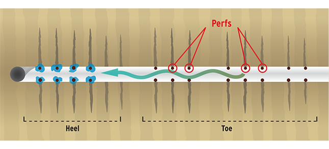 Figure 1: The process of plugging off the perforations and spreading the treatment throughout the lateral is illustrated.
This condition will continue until the pressure in the heel region is equal to that of the mid and toe sections. The upside of this process is that the mid and toe sections get a second chance at cleaning up. But the downside is that they will deposit their damaging fluids and materials in the heel.
Let's look at the composition and effects of this damaging fluid entering the heel:
• Mainly frac fluid with some reservoir fluids, mud, etc.
• Can contain solids, smaller proppants
• Allows scales to be formed due to migration and mixing of fluids
This process will increase the water saturation of the producing fractures to 100%. The process will also invade the fracture until a pressure equilibrium is met, but will not flood or invade the reservoir very deeply due to more force being required to do so, and the fracture, unless it has no conductivity, will be an easier flow path. The relationship to flow can then be quantified as:

This relationship says that the flow is directly proportional to the amount of drive behind it and the conductivity of the fracture** and inversely proportional to viscosity. An illustration — thick frac fluids in low conductivity fractures do not migrate well unless there is a very low-pressure region to which they can flow. Whereas gas, with 100th the viscosity of most reservoir fluids and 500th the viscosity of broken frac fluids, can flow quite easily.
**Here, the term k represents fracture conductivity. Later in this discussion, the term will represent reservoir perm and the effect is essentially the same.
Now the question becomes, what does this all mean? It can mean many things, most of which are not good:
• Once the wellbore becomes completely static, the saturation contrasts in the fractures are equal to gas, oil and water.
• When the well is finally opened up, assuming that no lifting aids (gas, pumps, etc.) are used to recover the fluids, the heel again will produce first and only possibly for a long period of time. The mid and toe sections will continue to be more able to flow into the heel fractures than to the surface.
• The production of the well should be expected to be at least 10% worse in terms of annualized decline rate. This is principally due to the increased water saturation (fluid imbibition), introduction of damaging materials from the mid-section and toe, and the redistribution of pressures.
• Once a lower pressure is developed in the target (the surface), then production can increase. Of course, putting the well on or increasing the degree of artificial lift will improve if not rectify this issue, but many wells are not appropriately equipped to handle that process at the degree that is required.
A solution to recover the well and re-establish pre shut-in production rates.
If your well has the fluid imbibition condition, you have 4 options to correct the situation. Each remedial treatment is intended to rectify the situation so that installing or increasing artificial lift is necessary. These remediations are ranked in terms of overall cost, from least expensive to most and with the cost comes the severity of the processes. The first option is to install or upgrade artificial lift.
Surfactant soak and re-wetting of the fracture conductivity.
By applying a Nano-surfactant style treatment, the fracture conductivity can be restored. The process changes the wettability of the proppant pack to water-wet allowing more hydrocarbon flow and reducing the resistance to flow by lowering the surface tension in the pack.
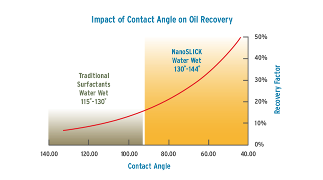
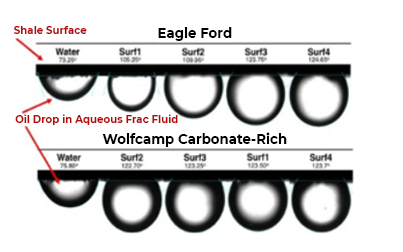 Figure 2: Contact angle has a huge impact on oil recovery. The lower the contact angle, the larger the contact patch between the oil and the formation walls. If the contact angle in the pore space can be modified, oil blobs turn into oil droplets which can be more easily swept through the pore space to the wellbore for collection.
Re-Perforating using sand-notching technologies.
In this case, it is necessary to prepare the well for intervention using coil tubing or hydraulic workover ('snubbing') equipment. A notching tool must be run on the end of coil or stiff pipe.
In the treating fluid, the same surfactant package as used in the previous illustration is applied after new perforations are notched using fine sand.
Re-Fracing the mid and toe sections using isolation packers with coil or stiff pipe.
One option in this process is to attempt to utilize the water blocking in the heel to encourage flow from the mid and toe sections of the well.
As in the previous illustration, the entire wellbore is cleaned-out and then small frac treatments using Friction Reducer fluids and 30/50 or 40/70 proppants to re-expose the reservoir to the wellbore. At the end of the treatments, it is advised to 'wash' the entire well with the Nano-fluid as well as jet the wellbore with gas to reduce the hydrostatic on the well which will improve load recovery. Of course, the process can be used to re-stimulate the heel, but remember that heel stimulation will discourage flow from the mid and toe sections.
Estimated costs.
In addition to any workover expenses, the following estimates are provided at June 2020 pricing:
• Surfactant soak and re-wetting of the fracture conductivity: USD $40,000 - $65,000
• Re-perforating using sand-notching technologies: USD $140,000 - $250,000
• Re-fracing the mid and toe sections using isolation packers with coil or stiff pipe: USD $200,000 - $375,000
As a reference, the links below will lead you to a discussion by industry-recognized experts on this issue.
SPE Live Panel Event: "Unconventionals: Shutting-in Production & Long-term Implications"
vimeo | youtube
facebook | facebook event
SPE Live: "AI in Energy — Resiliency and Efficiency Gains"
spe live event
Twitter and Periscope will also stream the broadcast.
(Links above will become available once the stream is live.)
By Lyle V. Lehman > November 2017
Frac Hits: What They are and How to Avoid Them —
It's Simple and Usually Easy
Frac Hits — when one frac treatment hits another older producing fracture in an offset well — is a hot topic. The November 2017 issue of JPT offers an article where they describe the process of a frac hit, accurately using the terms 'pressure sink' and 'parent and child' wells. In 2008 and 2009, we completed several horizontal wells (child) in the Granite Wash that were drilled between three vertical wells (parents) that had produced several BCF of gas over their life. Our geophones were in the parent wells. I recall observing microseismic events when a parent well was hit during three stages. In the first case, the fracture from the child rotated 45 degrees to hit the parent, in the second case the parent was along the maximum stress direction — thus a direct hit, and in the third case the frac rotation was only about 18 degrees. If you want to see a microseismic field engineer get upset, watch his/her reaction when the geophones are hit by a fracture. It's a pure moment of stress.
Some people will tell you that having a frac hit is not all bad for two reasons: 1) It means that the well spacing is optimized or even too close which may allow you to drain far outside the stimulated field, and 2) Some will cite references where the parent well came back to life producing more hydrocarbons after the well was recovered. This occurred in the Granite Wash cases. Contrary to that, others will cite the complete opposite, that the child's frac temporarily ruined or even permanently damaged the parent well's production. Still, a child hitting a parent is not a good thing as it always requires an intervention to recover. No pun intended.
The mechanism of the hit was discovered by Newton (ca. 1675) in the mythical apple incident, paraphrasing Newton's first law "everything in nature goes to its lowest energy state". In other words, the frac emitting from the child hits a producing fracture in the parent resulting in temporarily killing the production in the parent well. This is made possible by: proximity, volume of fluid, efficiency of the fluid and differing pressure regions. Knowing those facts offers the best keys to reducing or removing the hit possibility.
Here are some guidelines on mitigating hit risk:
• Blocking and tackling — check the near wellbore environment of the Child well. If you are pumping into 3 or more perforation clusters and experience a hit, chances are extremely high that only one of the clusters is taking fluid. By measuring the perforation opening and Tortuosity pressures by performing a step-rate test, one can determine how many holes are open and the fewer the holes, the higher the probability that a hit will occur. That's fairly simple mass balance, so in these situations a suggestion is to run ball sealers to open perforations.
• Under-design your treatments. This can be performed in several methods. You can of course just pump lower volumes of fluid, but you can also pump the volume that you would in a 3-cluster treatment over 5 clusters. Of course, point #1 needs to be observed and you jeopardize treating all clusters anytime that you exceed three intended frac exit points.
• Stagger the landing points between wells. I read this idea in the JPT article and think that it is not necessarily the best idea as pumping enough volume will make up the difference in frac height. Staggering probably brings into light other completion effects that don't affect hits, but could be better for other reasons, such as having a better access to the proppant bank that is being built in the fracture.
• Shut-in the parent well as long as you can before fracing the child. One of our clients in the Haynesville used to drill their entire pad before starting the frac program and then, only after the last pad was fraced, did they start load recovery. They seldom (if ever) experienced hits.
• My new favorite — Run stages/ramps with diverters at the end of the higher proppant concentration. This is probably the most positive method offered and it really can be done without performing analysis (assuming that you/your service company/consultant do not know how to analyze the effectiveness of diverter). Simply run as many stages as you have perf clusters like this: Pad, start 0.5 ppa ramping to 2.5 ppa (or higher if you are using real gel) then place a stage of diverter designed to seal-off a cluster, then repeat until you have pumped as many stages as you have clusters. Note: slow down when the diverter hits so it can 'seat' and do not run diverter in the last stage/ramp. I do actually recommend analysis and that it be done in real-time, but I know that the talent to do that may not exist in your neck of the woods. However, doing this technique is better than expecting something different from your stimulation program.
The best solution to preventing hits is to model-analyze-model the reservoir to determine how much depletion is required to allow a hit to occur. The only caveat here is that any natural flaws or pathways in the reservoir usually are not detected and they certainly outweigh any mitigation method.
By Lyle V. Lehman > February 2017
How Not to Run Diversion in a Multi-Cluster Frac Stage
Frac Diagnostics recently analyzed a long horizontal well in SE Oklahoma. The client had perforated 6 clusters over 320 feet of lateral with 6 holes per cluster spaced evenly apart. They performed the frac treatment by taking a rather large volume of fluid and sand, then cutting the treatment in thirds. In between the thirds, they ran 10 biodegradable ball sealers. All stages were the same in cookie-cutter fashion. This is a prime example of how not to run diversion.
Figure 1: The Bottom Hole Pressure Match of an example frac stage on the subject well illustrating Surface Treatment Data and Downhole Interpretation of the data. The top panel has surface treating pressure (psig) in white, injection rate (BPM) in yellow, surface proppant (ppa) in violet. Bottom panel has the interpretation of bottom hole conditions with the actual bottom hole treating pressure (psig) in blue, model match of bottom hole pressure (psig) in red and bottom hole proppant concentration (ppa) in light green.
Figure 1 above is an example stage of a well that Frac Diagnostics analyzed. This stage had 6 clusters, so was perforated 36 times. At pump time 3386 minutes, you will see the rate drop as they flushed the first third of the treatment with 10 ball sealers at the beginning of the flush.
Right here you should ask, "Why 10 ball sealers?" We asked that same question and the answer is that ball sealer efficiency is usually two-thirds of the desired result. Meaning, they wanted to seal-off 6 holes so they ran 10 balls (and I know that 6 X 1.5 = 9, but they ran 10). The rule-of-thumb is that when you are breaking down a zone and wish to open perforations, then you run 1.5 times of balls as the number of perforations. Whereas if you wish to divert a frac stage, you run 1 times the number of perforations that you wish to block, but only after you measure the number of perforations that are open.
If you will notice, this stage does not have a step-rate test in the front so that the onsite engineers could determine how many holes are open.
That issue alone is a good example of how not to run diversion, but take another look at the figure. At pump time 3394 minutes, the balls hit their targets which — you guessed it — indicate a 10-perforation loss; then at pump time 3403 minutes, the balls are knocked-off by the second stage proppant passing through the clusters.
Now you should ask, "After all that diversion and then release of diversion, what was actually accomplished?" The answer is fairly complicated but by using inductive diagnostics, of the original 36 holes, only 24 actually were taking fluid initially. There was a bit of Tortuosity (that pressure decreased from 3361 to 3366 minutes) but the first ball sealer drop reduced the effective perforations to 14, then the proppant returned them to 24, then the next wave of ball sealers returned them to 14 and after some relief, it appears that some complexity allowed some of the perforations to screenout as the friction pressures solve to only 7 open by the end of the treatment.
In Frac Diagnostic's opinion, the reason to divert is to place proppant in zones that do not normally receive proppant and can add increased production. In this case that goal is difficult to analyze. Data indicates that the pre-ball sealer and post-ball sealer episodes yield identical reservoir conditions. With 320 feet of total stage spacing, the probability of a measurable change in rock characteristics is high.
Therefore mission not accomplished.
What would Frac Diagnostics do differently?
1. We would measure the number of holes open. You have to know what the near wellbore conditions are and if you need to be prepared to mitigate any unforeseen issues.
2. We would not run ball sealers in a horizontal well and expect diversion to survive. That scenario just cannot happen.
3. We would use polylactic acid or similar diverters as they tend to penetrate the perforations and seal into the formation. These materials deform and temporarily plug access into the formation.
4. We would use variable injection rates if needed to get selective plugging of perforations. Remember that the lowest pressure drop favors the heel cluster so it probably is taking more fluid than you would like.
5. We would measure the effect of the diversion by performing real-time or post stage analytics.
By Lyle V. Lehman > January 2017
The Lost Art of Net Pressure Matching
Why it is more important now than before
Not so many years ago when the oilfield was vertical, we spent a lot of time analyzing data, designing completions and developing a lot of 'best practices' by paying attention to the stimulation processes and procedures. There was an emerging market in stimulation
consulting — principally led by S.A. Holditch and Company — to whom we owe a debt of gratitude. Their efforts showed us that by adding an expert to observe and engineer the frac treatments rather than relying on regular field operations people, the treatments could be altered in real-time and therefore made more successful. That is the 'nut shell' definition of the scope of the stimulation consultant of that era.
Many post-treatment analyses were performed and we could learn from the data with updates from actual production to determine effective frac geometries and the probable need to improve conductivity by using more optimized fluids and proppants. For the more successful operators, this was a normal process, until around 2007.
That's when the majority of the oilfield went sideways.
One benefit from going sideways is that oil operators are able to develop and then exploit the hydrocarbon source rocks themselves. Two attributes of these reservoirs are: 1.) They were never considered 'reservoirs' before, and 2.) They require a lot of fracing and reservoir contact to make them produce hydrocarbons at economic rates. Along with these benefits came several operational distractors. One is germane to this discussion: Instead of performing a frac treatment once into the pay zone as in a vertical well, the pay zone is fraced 12, 24, 36, up to 78 times, by recent tallies, along the extended horizontal wellbore. This required on site frac activities to take place around the clock rather than only in daylight, which allowed 4 to 8 treatments per day to be performed. Productivity was measured by how many pounds of proppant, gallons of water, perforation runs, plug set or sleeves opened, catered meals, etc. were used per day.
But one practice was quickly cast aside in this new horizontal age: The engineering analysis of the frac treatments. The key element being net pressure matching of real data using a frac model to determine the actual attributes of the frac treatment and yielding results which could be used to alter the current stage — if done in real time — or future stages or even wells in the same field. Stated another way, the operators and service companies succumbed to purchasing agents who drove the process toward economics in the field with complete disregard for analyzing data and improving production results. The mantra became, "if it does not produce projected results, then we need more pounds of proppant per foot" instead of understanding the reservoir capacity and the effect that the completion was having on production.
Net Pressure Matching (NPM) is more of an art than a science because in most cases we use surface treating data which is subject to pipe and other friction issues. However, in skilled, experienced hands the practice can convey many issues that address the level of production as observed by the oil and gas runs to the refinery.
Following are some issues that NPM can unveil:
• Perforations open and level of Tortuosity
• Early detection of back-stress
• Effect of diversion materials and their functional periods or activity levels
• Narrow range of reservoir permeability
• Close proximity of, if not a correct value of, fracture closure
• Proppant Placement Geometry — based on model bias
From these conclusions, one can determine if fracture spacing is adequate, if zones should be skipped, if more or less proppant should be run, and if perforating in general needs to be augmented — the list is very long.
The final aspect of this thesis is to know who is capable of performing a net pressure match and I must tell you that the list is very short. An operator who seeks to understand how to optimize their completions by using net pressure matching needs someone who is in the practice of performing this diagnostic step almost daily. In terms of skill, this is near the highest level required for a stimulation analyst. To give the reader a calibration, the skills involved in properly designing a frac treatment require anywhere between 4 months to 2 years of study. Design is viewed as more of an academic role and after one gets the knack of designing frac treatments, they should be able to create a design on the back of the envelope that their electricity bill arrived in. Analysis of data is different and again this gets us back to the main criticism of using surface treating data. One has to understand the cause and effect relationships of pressure responses to determine if the increase/decrease in pressure is from the formation or some friction reducer additive that suddenly was turned off or up. Performing net pressure matching in real-time is the highest skill level practiced and appreciated by the stimulation diagnostician peers.
In closing, the goal of a successful completion is to place a wellbore in the pay zone then create an access to it in such a fashion that hydrocarbons can be recovered in an economic manner at the highest possible rate of return and recovery. Understanding the reservoir and the completion through net pressure matching will illuminate and remove doubt in the broad areas that the completion engineer can improve from well to well.
By Lyle V. Lehman > June 2016
Understanding the Roles of Conductivity, Contact and Continuity in the Fracturing Process, Part 1
This first blog will deal with the roll of Conductivity. As I have been associated with suppliers of excellent conductivity, I feel very comfortable speaking about the benefits of conductivity. Simply stated, conductivity is what you pay for when you buy a frac treatment. You are attempting to place a conductive channel that leads from deep into the reservoir and connects the wellbore, which ultimately allows higher levels of production than if no pathway was placed. This simplified task has many many distractions which must be dealt with and we will address them periodically as the months move along.
But the topic is Conductivity and my main point of reference is from Claude Cook who (famously) said, "You can never be too young, too rich or have enough conductivity" which translates to: there is no penalty for having too much conductivity. But is there?
After analyzing frac treatments and then examining production, I still agree with Claude's observation, but what I must alarm you about is the means of placing conductivity. It seems that some reservoirs, the Wolfcamp being a prime example, do not appear to like conductivity. They actually do benefit from conductivity but not in the way that we normally interpret the benefit. After all, these are unconventional reservoirs and they have their own set of rules, one of which is (and this is the most important part) that the damage inflicted by placing high levels of conductivity will damage the proppant pack to the point that the pack cannot unload the frac fluid and thus yields a very shortened pack.
So what is my advice? First of all, if you want to share some data on an issue similar to this, please write me. But my advice is to use the lowest dosage of viscosity needed to place conductivity. I do not condone mass amounts of 100 mesh as we will discuss that in the next blog.
By Lyle V. Lehman > July 2016
Understanding the Roles of Conductivity, Contact and Continuity in the Fracturing Process, Part 2
In Part 1, I discussed the important role of conductivity and how it must be adequately placed to benefit production. One issue raised was the impact of using excess gel materials to place conductivity and that brings us to the importance of contact.
Simply stated, 'contact' is the frequency which a fracture is placed in a lateral wellbore. An illustration of this is the current debate about perforating every XXX feet. If you follow the daily news items, you will recall how some aggressive operators announce that they have increased their perforation frequency from one cluster every 250 feet to 200 then 150 then 100 then 75 feet. Thus if you have a 5000-foot lateral, you may originally have performed 21 individual frac treatments but eventually increased to 68 treatments. In either case, this is a clear illustration of increasing reservoir contact to generate more production.
The actual issue though is not as simple. "How often do I need to frac and How is each frac best designed?" In other words, if you increase your frequency 3-fold as in the illustration above, do you change the frac treatment? I say it depends on your original treatment design.
We see many cases where 100 mesh sand is used - hang on to your hat - as a substitute for gel. We performed a study in the Marcellus a few years ago where the client offered compelling data stating that wells which used 100 mesh had slightly better Initial Potentials (IP's) but clearly better estimated ultimate recovery (EUR) values over those that used little if any 100 mesh and gel. The caveat here is that no baseline was established which indicated if the reservoirs were better or worse in either case - but that did not matter with the client.
My observation was that 100 mesh was performing the same duty in the fracture as the gel, thus it was a substitute. A second caveat was that the client also stimulated an entire pad of wells only using 100 mesh and the wells suffered both in IP and EUR.
Conclusion: Pick your targets wisely because the proper blend of cluster spacing is not the entire issue; the frac design and knowing the regions of the wellbore (where the stress and perm changes lie) will dictate success or failure.
By Lyle V. Lehman > August 2016
Understanding the Roles of Conductivity, Contact and Continuity in the Fracturing Process, Part 3
In the previous blogs I discussed the role of conductivity and then reservoir contact — also known as frequency of fracturing — and in this blog I will discuss continuity. This area is possibly the least regarded in the completion of horizontal wells. Some call it connectivity and that may be a more specific term, but I prefer to also include the notion of being more properly disciplined in the entire completion process, thus including more things in the quality assurance world. Again, bear in mind that we are discussing horizontal wells in unconventional reservoirs.
Figure 1: two cases of flushing and overflushing
Figure 1 at left illustrates two cases where a frac stage was flushed. The case on the left indicates that the stage was overflushed (notice the orange bottom hole density line returning to 0 before shut down). The plot on the right illustrates a case where the well was properly flushed. Most completion engineers today advocate the process on the left so they can achieve unobstructed perforation gun 'travel' to set a plug for the previous stage and then perforate the next stage. Sticking a gun costs $$$ and this should be avoided. However, the process of overflushing must be performed to assure gun travel.
So what is the impact of overflushing? Recall that many experts cite only 40 to 60% of perforation clusters actually contribute to production. That is a very powerful claim and I am certain that many production logging procedures have unveiled and supported this claim. But the real question is why?
The 'why' part can be answered by considering the potential failure mechanisms.
Here is our rogue's gallery of failure mechanisms for failed cluster contribution:
• Cluster did not open when the stage was pumped — my all-time favorite thing to blame (and which I will address in an upcoming Frac Tip);
• Overflushing due to running guns in the hole — another good reason but the one that no one talks about (sort of like the 500-pound gorilla in the room that is always ignored); and
• Overflushing the stage per SOP's — this is our subject and I am sure everyone now sees that in the case of the quoted span of 40 to 60% of this could be the sole cause of the failures and you can easily get to 60% failure rate by including cluster breakdown issues per the first bullet.
Take a look at SPE 170743 and 179163 by Wadhah Al-Tailji. He not only makes a compelling case against over-flushing, he also offers a solution which allows you to flush properly, pump your guns down and keep the connectivity intact in the clusters.
Figure 2: production comparison in overflush study
In Figure 2 above, Al-Tailji offers compelling evidence that his technique works by illustrating the differences in 1-year production from 52 wells that commonly used overflushing to secure gun travel, versus 8 wells which used his technique of overflush minimization (versus area coverage). To get the details please read his 170743 paper.
My advice? To quote my Mentor Bob Hannah, "The first rule of engineering is to never beg a problem." Meaning, take all steps necessary to alleviate these issues.